No.2 new District Minglun Village,Wuxiang Town,Yinzhou District
-

Tel: +86 18658447778
-

E-mail: [email protected]
-


Structural Composition
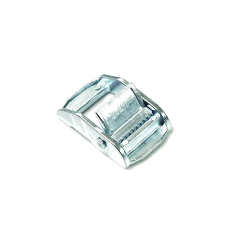
Alloy Shell: Typically zinc alloy/aluminum alloy, combining lightweight and high strength
Cam Core: Precision-machined eccentric cam that generates radial pressure during rotation
Locking Groove: Interlocks with the slot in the matching bracket
Anti-loosening Washer (Optional): Prevents accidental loosening due to vibration
Workflow
Alignment: Insert the cam buckle into the pre-set mounting hole
Rotation: Locks with a 90° turn (some models support 180°)
Self-locking: The eccentric cam structure generates continuous clamping force
Key Performance Advantages
Efficiency Improvement: Installation is 3-5 times faster than traditional bolts
Tool-Free Operation: Easy to install and remove by hand
Vibration Resistance: Maintains locking force under dynamic loads
Corrosion Resistance: Chrome plating/anodized finish available
Load Capacity: Static loads of up to 5-8 kN per buckle
Typical Applications
Industrial ▸ Rapid fastening of mechanical equipment access panels ▸ Module connections in automated production lines
Construction ▸ Temporary support point locking for steel structures ▸ Prefabricated building component docking
Transportation ▸ Rail transit interior component installation ▸ New energy vehicle battery compartment cover fixing
Causes:
Cam not fully rotated (locking angle not reached).
Worn or mismatched mounting bracket slots.
Vibrating environment causing self-locking failure.
Solution: Confirm that the cam is rotated until a "click" locks (usually 90° or 180°).
Inspect the mounting bracket slots for deformation and replace if necessary.
Select a model with a lock washer or nylon self-locking.
Causes:
Cam and bracket fit too tightly.
Installation angle deviation leading to uneven force.
Surface coating thickening (e.g., after painting).
Solution:
Manually run-in the cam 3-5 times before first use.
Lightly tap with a rubber hammer to adjust alignment, then rotate again.
Remove excess coating or use a high-torque assist tool.
Causes:
Worn cam teeth (over 500 cycles of frequent use).
Fatigue deformation of the alloy material.
Solution:
Inspect regularly and replace when life expires.
Select a reinforced model with a steel cam core.
Cause:
Aluminum alloy material is not surface treated
Salt spray/chemical corrosion
Solution:
Preferably select nickel-plated or anodized models
Apply anti-rust grease regularly
Cause:
Manufacturing tolerance accumulation
Bracket deformation caused by long-term load
Solution:
Use an adjustable bracket (such as one with an elastic bushing)
Install a 0.1-0.3mm stainless steel gasket inside the bracket
Cause:
Aluminum alloy strength decreases above 150°C
Plastic locking element melts
Solution:
Switch to stainless steel (temperature resistant 400°C+)
Remove plastic components and use a metal locking mechanism
Cause:
Vibration frequency resonates with the self-locking mechanism
Unrated torque not achieved
Solution:
Use a product with a secondary locking mechanism
Add a spring steel stopper
Cause:
Cam rotation radius interferes with surrounding components
Solution:
Use a push-pull quick-release buckle
Customize a small-angle (45°) locking version
Cause:
Non-planar contact causes stress concentration
Solution: Use a floating cam buckle (±2mm tolerance allowed)
Add a special-shaped adapter bracket
Cause:
Overload caused by violent operation
Material casting defects
Solution:
Use a dedicated disassembly tool
Require a material report (EN 1706 standard) when purchasing